Grade Control: Beyond the Magic
It wasn’t all that long ago that fleet managers, maintenance supervisors, and equipment technicians walking around shows like Conexpo didn’t miss a step as they passed by the construction-technology exhibitors’ booths. Newfangled things like grade control systems were “just another thing to break.” That’s changed.
“I can see the tide turning,” says Matt McLean, a product manager at Volvo. Experts from other OEMs also report a similar trend. Contractors are transitioning into machine-control technology, and McLean says they now come armed with lists of ideas and applications they would like to add to their own fleet’s competencies, actively seeking out construction-technology companies that have the grading systems and expertise to bring that contractor’s list to reality.
How to Keep Grade Control Systems Working
Komatsu’s senior product manager, Jason Anetsberger, says the contractors he talks with now are past their initial hesitation to commit to new technology systems and are ready to make their move. “Contractors are no longer viewing the machine and its technology as separate entities.”
Machine control gains ground
The acceptance of grade control system growth points to several things. Upgraded operator training is polishing operators’ mechanical operating skills and teaching them how to use sophisticated electronics. OEMs are partnering with technology manufacturers such as Trimble and Topcon to develop control products that complement each other. And now, innovative positioning science is giving users what they really want on their grading jobs: precise, dead-certain accuracy.
Automatic grade control (AGC) systems on dozers, graders, and excavators bring enormous benefits to contractors in terms of vastly improved accuracy, fewer workers required for the job, higher production rates, and access to bidding opportunities that specify grade-control technology.
This greatly improved accuracy of the modern grade-control system is made possible by a whole different breed of motion sensor. The same sensor smarts used in aviation navigation and by NASA is now bolted on dozers, graders, and excavators. Called inertial measurement units (IMUs), these multifunction sensors read changes in motion activity like standard simple sensors, then enhance those readings to provide a third dimension of positioning data at lightning-fast speeds.
The heart of the grade control system is its awareness of where the machine is in relation to its environment—its location. Location-tracking GPS systems on heavy equipment have proven to be hugely valuable for many fleets, but GPS-based technology has limitations such as signal blockages, slow update rates, and an accuracy of 1 meter that might not provide sufficient data for some control applications. Integrating IMUs into an equipment-control platform complements the existing GPS locating technology in such a way that the IMU helps overcome these GPS limitations. Here’s how:
First, remember that GPS detects only location. As each GPS location ping is added to the previous ping, it is possible to calculate an object’s location and the direction from which it came.
IMUs measure movement
No matter how complex the motion, any possible movement of a rigid object in space (such as a grader blade or excavator bucket) can be measured and expressed as a combination of the Six Degrees of Freedom (DOF). There are three DOF for linear movement—forward/back, up/down, left/right—and three DOF for rotation—pitch, yaw, and roll.
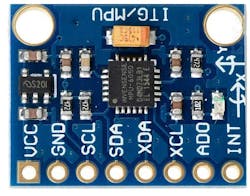
The IMU measures movement using a combination of up to four microelectromechanical motion sensors that detect those six DOF physical motions. Each tiny sensor is mounted on one small green computer board and wired to a serial port. The four sensors contained in most IMUs are:
The gyroscope sensor measures angular position changes independently from gravity, such as twisting and rotation, to determine an object’s orientation within a 3D space and changes in that orientation while in motion. Gyroscope sensors are available with one, two, or three axes corresponding to pitch, roll, and yaw angles
The accelerometer sensor measures linear acceleration, including acceleration caused by the device’s motion and acceleration due to gravity. Accelerometer data can be used to measure static device orientation.
The magnetometer senses magnetic North and measures the strength of the magnetic field. Computing the angle of the detected magnetic field and comparing that measured angle to gravity measured by the accelerometer will give the direction the sensor is heading.
The pressure sensor measures changes in ambient air pressure. When that measurement is compared to standard atmospheric pressure at sea level it can be used to track vertical motion.
Using a process called sensor fusion (a mathematical algorithm that resides in the IMU programming), the IMU takes the data outputs of the four sensors and calculates a highly accurate estimate of where an object is in relation to its environment, how it is positioned in its space, what direction it is facing, and its speed based on a known starting point. The IMU adds orientation to the GPS data.
IMUs further complement the GPS system with much more rapid updates. GPS updates its location data once a second, which in continuous positioning terms is pretty coarse. An IMU can update hundreds of times during the same span, leaving less room between measurements. This means the data stream used by the grade control system’s application software is saturated with more fresh, real-time readings and enriched with 360-degree measurements. The IMU data fills in the GPS limitations and in effect boosts its accuracy.
Grade control accuracy can also be impacted by GPS signal limitations. GNSS signals are directional and can be blocked by buildings and natural obstructions. GPS signals won’t work in urban canyons or underground. IMUs don’t rely on external signal transmission so their data can be generated underground, in tunnels, or wherever else physical interference blocks GPS signals.
IMUs are rugged enough to be installed just about anywhere on a dozer, grader, or excavator. You’ll find them on grader and dozer blades, on the undercarriage frame, on the body, and mounted internally. The location depends on the task and the manufacturer’s preference.
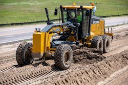
Grade control in roadbuilding
John Deere’s lineup of SmartGrade motorgraders all utilize in-cylinder position sensing to accurately control the cutting edge of the moldboard.
“The use of high-accuracy in-cylinder position sensing technology in combination with information on the machine, allows the SmartGrade grader to...maintain precision grading accuracy, significantly increasing the operator’s efficiency,” says Deere’s Sean Mairet, grade control product marketing manager. He adds that sealing the sensor in-cylinder protects it from debris and potential damage.
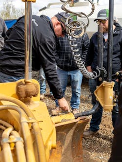
Locating the positioning sensor in the cylinder sometimes raises the question of how to perform maintenance work on the cylinder without harming the sensor. Mairet says Deere has simplified reinstalling the in-cylinder sensor by putting an RFID tag on it with all the information the control system needs to automatically recalibrate. The tech just enters the tag’s information and the sensor returns to active duty.
Other manufacturers such as Caterpillar prefer to locate sensors externally. Cat’s IMUs are bolted on and are easily removed if necessary for general maintenance procedures. When the IMU is bolted back on, Cat’s grade system automatically identifies the sensor, a process similar to syncing Bluetooth devices.